feb 07, 2024
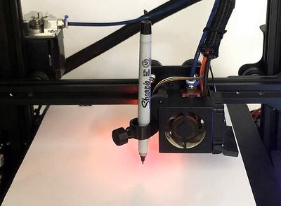
🔗 Convert a 3D printer into a pen plotter
I wanted to add to my 3D printer the ability to pick up a pen and start drawing.
Luckily, today it's pretty easy to use a 3D printer as a pen plotter. The process is very simple since the printer is already a CNC machine to which you can mount a pen holder, maybe even print a custom one.
# Build requirements
I custom designed the pen holder because I wanted to be able to:
- use it without removing the plastic extruder,
- take it off easily when it's not needed,
- plus it had to fit next to the BLTouch sensor
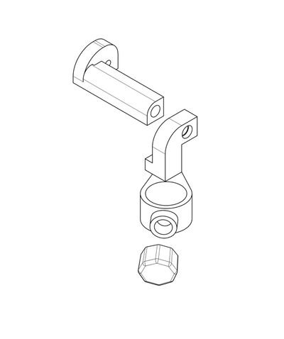 The final design of the pen holder.
As depicted in the picture, the pen holder is made of two main parts:
- a base, which is attached permanently onto the extruder box,
- the pen holder, attached to the base, which can be removed or replaced by just unscrewing the bolt on the front.
There are heat set inserts on both pieces sides to make the assembly easier and more robust. The pen holder is designed to hold any pen, brush, tool with a diameter of 15 mm, but it can be interchanged with a different one by just changing the pen holder part.
# Generate G-code from SVG files
To draw with a 3D printer, as for any laser-cutter or CNC machine, a vector drawing has to be converted into machine-readable G-code. Most existing workflows are based on the use of Inkscape, a free and open-source vector graphics editor, paired with a plugin.
There are a few plugins available that do this, these seem to be the most popular:
- evil-mad/axidraw the companion software for AxiDraw machines, which should work for any CNC machine,
- JTechPhotonics/J-Tech-Photonics-Laser-Tool, plugin specialized for laser engraving,
- cnc-club/gcodetools, a solid plugin that comes bundled with the application.
Here I'm using the latter because it looked like the most complete solution, and since it's bundled with Inkscape, it's likely to be the most stable and well-maintained long-term.
# Document setup
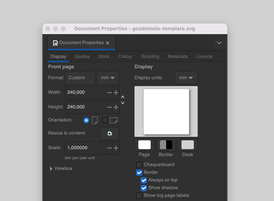
The first step is to set up the document to match the printer's bed size. The bed size of my Ender 3 is 240x240 mm, so in the Document Properties panel, set the document to the same size, set the document units to mm and the Scale to 1.
# Extension settings
The Gcodetools extension comes bundled with Inkscape and can be found under Extensions > Gcodetools. The extension has a few settings that need to be configured before generating the GCode.
Select tool
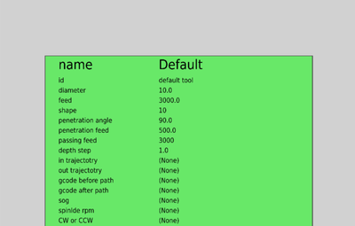
First of all, the Gcodetools extension needs a tool to be defined, to create a default one, go to Extensions > Gcodetools > Tools Library..
Select the Default and click Apply. The extension will create a new layer with the tool's settings, which can be edited by double-clicking on the layer. I suggest increasing the Feed rate to 3000, since a pen-plotter can move faster than a CNC machine.
Orientation points
The next step is to create the Orientation Points which will give the extension the reference points needed to produce the GCode. Go to Extensions > Gcodetools > Orientation Points.. From the settings panel pick 2-points mode and click Apply.
The extension will create a new layer with the orientation points, which can be edited by double-clicking on the layer. The points should be placed at the bottom-left and bottom-right corners of the artboard.
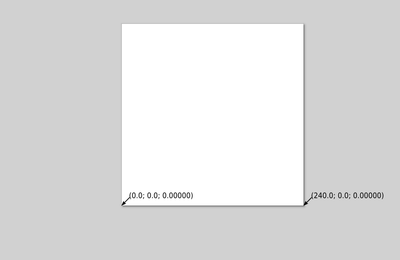
By testing and measuring the distance between the pen-holder and the hotend extruder, you should find that there is a small offset in the X and Y axis between the vector file and the physical drawing . This can be corrected by either moving the orientation points or by changing their values by double-clicking on the layer.
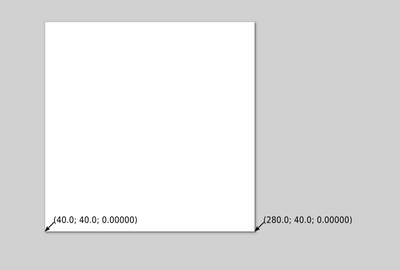
Generate G-code
The last step is to generate the GCode. To do so all vector objects need first to be converted to a path, select them and go to Path > Object to Path. These need to be in the same layer as the orientation points.
⚠️ Warning:
The new paths need to be in the same layer as the orientation points.
Now to Extensions > Gcodetools > Path to Gcode.. and it will open a new panel with a few settings to be tweaked according to one's needs.
Those are the settings I changed from the default ones:
- change the output extension to
.gcodeinstead of.ngc, by changing the Output file name tooutput.gcode, because Octoprint will only recognize that one as a valid extension, - set the Offest along Z axis to
-1because the toolDepth stepis set to1, but changing it to0will throw an error
Gcodetools allows to set custom Header and a Footer in the output file, which can be useful to set custom commands.
⚠️ Warning:
To set custom header and footer, we need to create two files in the output folder, without extensions, named
headerandfooter.
This is my custom header:
M420 S1 ; Enable Jyers Mesh
M75 ; Start print timer
G28 ; home all axis

G01 Z0.100000
M0 ; Pause to set pen height
And this is my custom footer:
G1 Z20.00 F600 ; Move print head up
G1 X5 Y180 F9000 ; present print
M84 X Y E ; disable motors
M77 ; Stop print timer
I found useful to add the M0 command in the header to pause the print while I set the pen height and tighten the pen holder screw.
⚠️ Warning:
Note that Octoprint by default actually blocks the
M0Pause command from being sent to the printer. Instead it performs a software pause from within Octoprint which works just as fine, the only difference is that the Resume command needs to come from Octoprint, instead that from the printer LCD panel.
Now click Apply to generate the GCode.
# Resources
- Inkscape
- G-code
- NC Viewer
- Ender 3 v2 Pen Plotter
- Octoprint can draw, too
- Inkscape for GCODE generation - quick instructions to get started
- cnc-club/gcodetools
- JTechPhotonics/J-Tech-Photonics-Laser-Tool
- evil-mad/axidraw
- appliedengdesign/vscode-gcode-syntax
- [Request] Option to allow sending of M0/M1 to the printer #1513